
A compact Nano-based interface PCB for LocoNet and WS2812B signal control.
LocoNet | Arduino Interface
Since I don’t really have space for a full model railway layout, I tend to tinker with small rail-related projects. One part I genuinely enjoy is automation. Bridging the physical and digital worlds is a lot of fun.
Because I use Uhlenbrock equipment, LocoNet is a natural fit.

LocoNet is part of a DCC train control system designed by Digitrax. It is a peer-to-peer local area network built for high traffic capacity, flexible wiring, and easy expansion. It is separate from the track power circuit that drives the trains.
Digitrax developed LocoNet to handle communication between throttles, stationary decoders, and other devices that need to talk to the command station.
Digitrax also works with companies that build LocoNet-compatible products. That gives users more choice in hardware and software for building the layout they want. To produce a commercial LocoNet product, you need a license from Digitrax. Fortunately, Digitrax also offers a personal edition license.
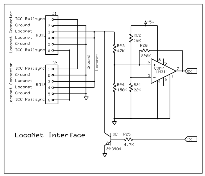
Interfacing an Arduino with LocoNet is straightforward using the Model Railroading with Arduino library. The hardware side is not difficult either, but prototype breadboards with loose wires get old quickly.
I have two GCA185 LocoNet shields by Peter Giling. They work great, but the standard Arduino form factor is a bit too large for what I wanted.
So I designed a custom interface PCB in Eagle CAD for the Arduino Nano. I removed the D-SUB9 connectors and added selectable I2C pull-up resistors via jumpers. That makes this interface usable with almost any I2C device, such as an MCP23008 or MCP23016 for I/O, or an OLED/LCD display.
I also added a connector for a PCA9685. The PCA9685 is an I2C-controlled PWM driver with an onboard clock. Unlike the TLC5940 family, it does not require continuous signal updates, so your microcontroller stays free for other work.

It is 5V compliant, which means you can control it from a 3.3V microcontroller while still safely driving up to 6V outputs. It also has 6 address-select pins, so you can connect up to 62 boards on one I2C bus: 992 outputs in total.
I also made SDA/SCL swappable to D5/D6 using jumpers. In the YouTube video below, I used this to connect a few WS2812B RGB LEDs to create low-cost railway signals, perfect for use in a sub-level staging area.
Build Gallery
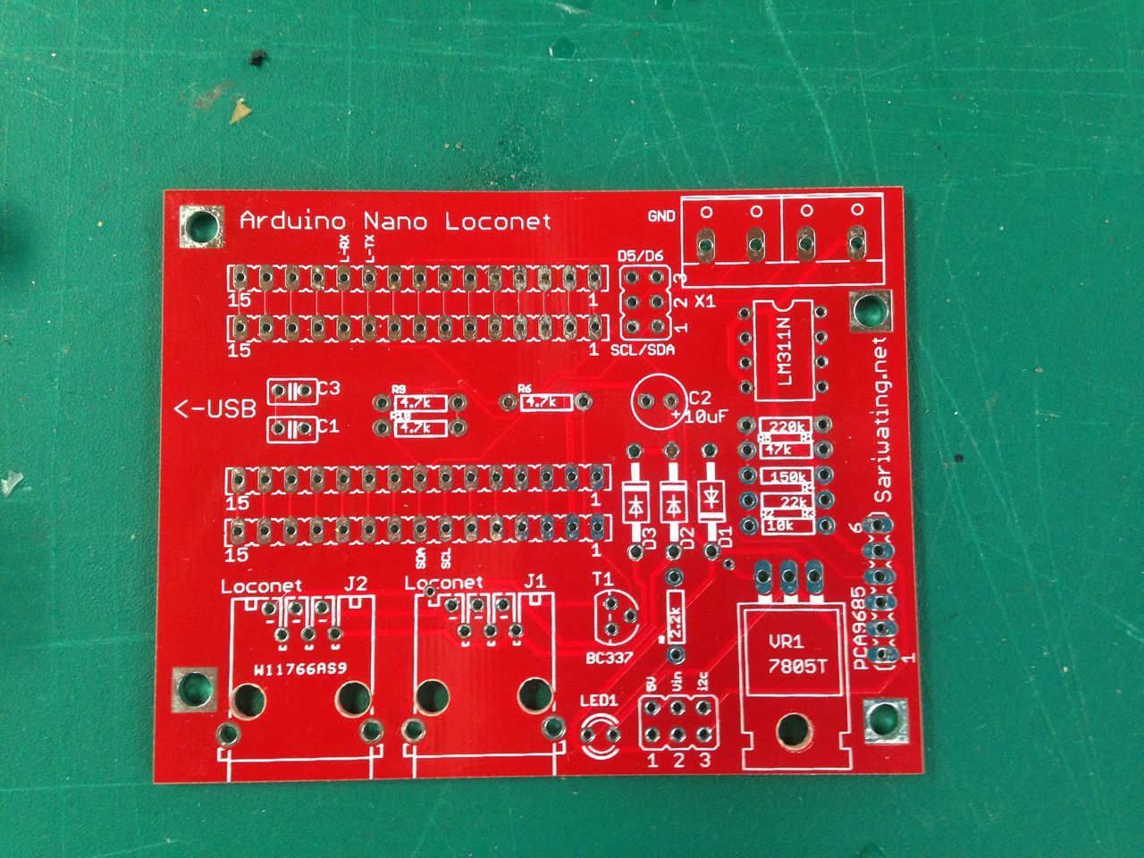 The LocoNet interface PCB I designed.
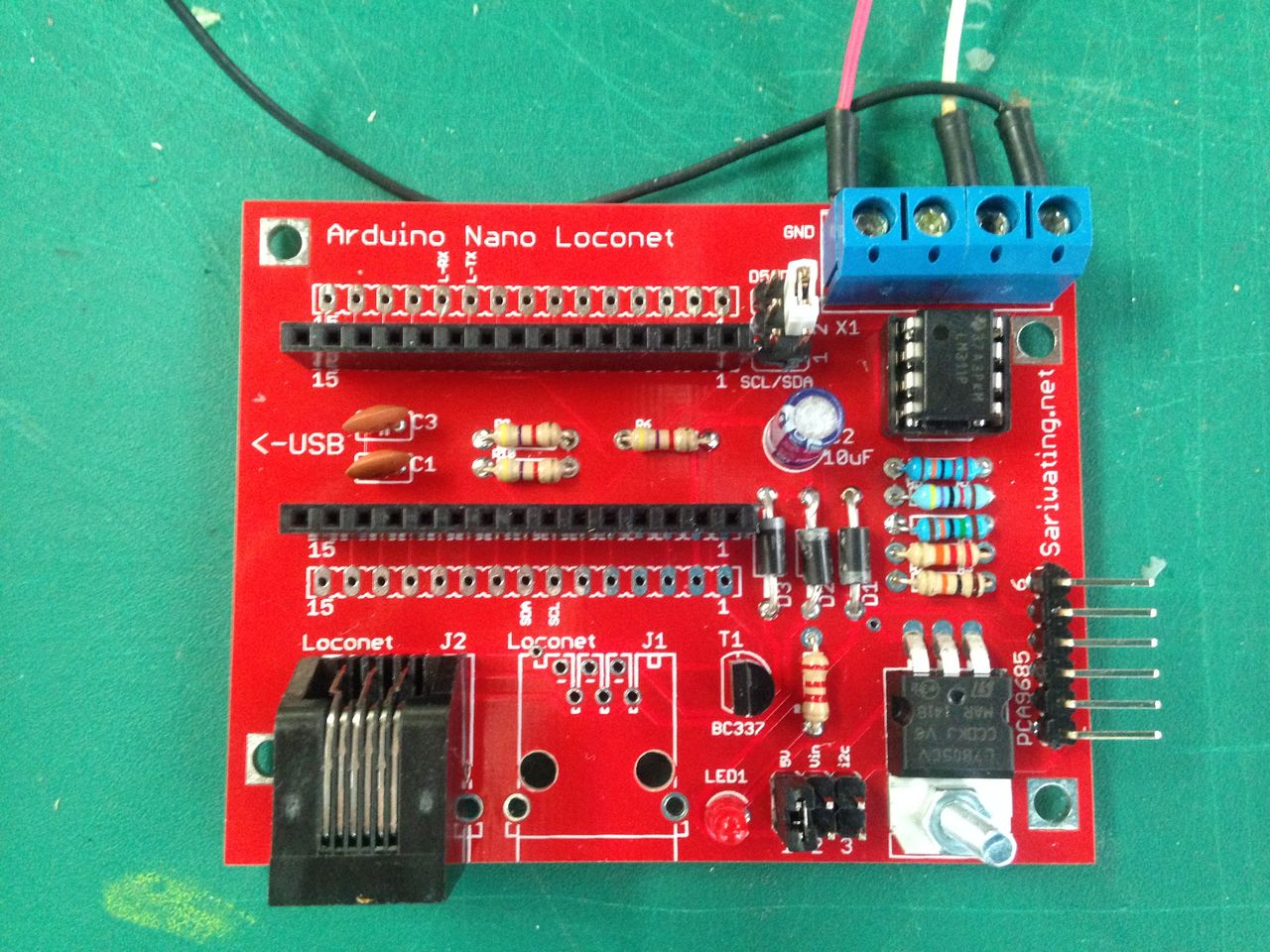 Blue connector pinout (left to right): 5V, SCL/D5, SDA/D6, GND.
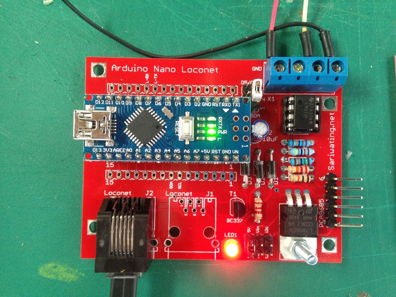 Looking good.
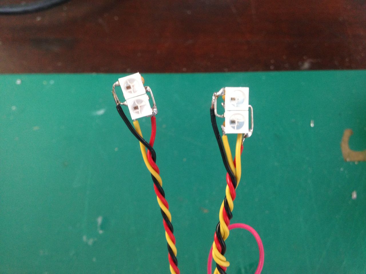 WS2812B LEDs soldered together as simple signals.
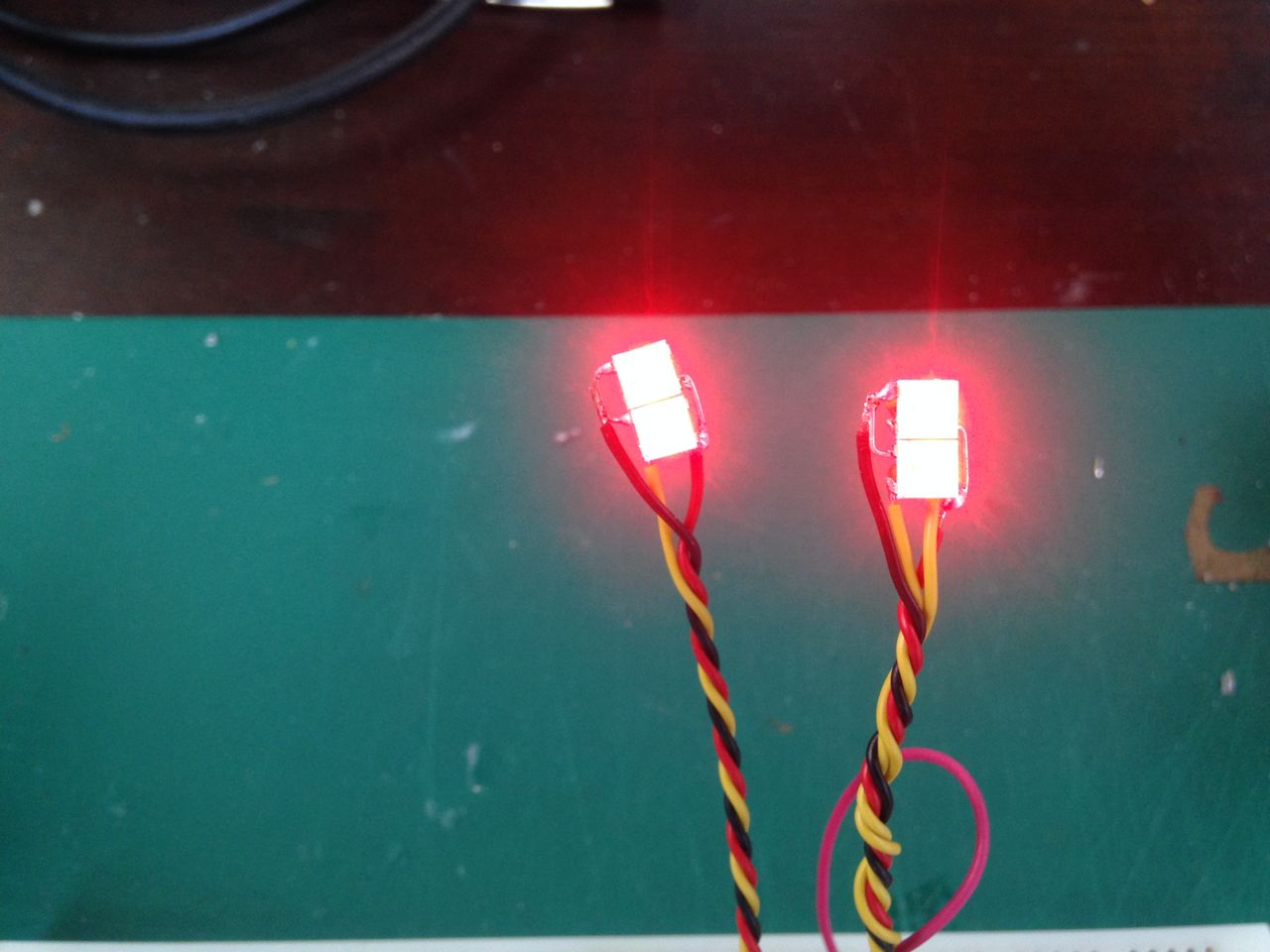 Individually controllable from the Arduino.
The code for the WS2812B simple signals is on GitHub.